SAR Description

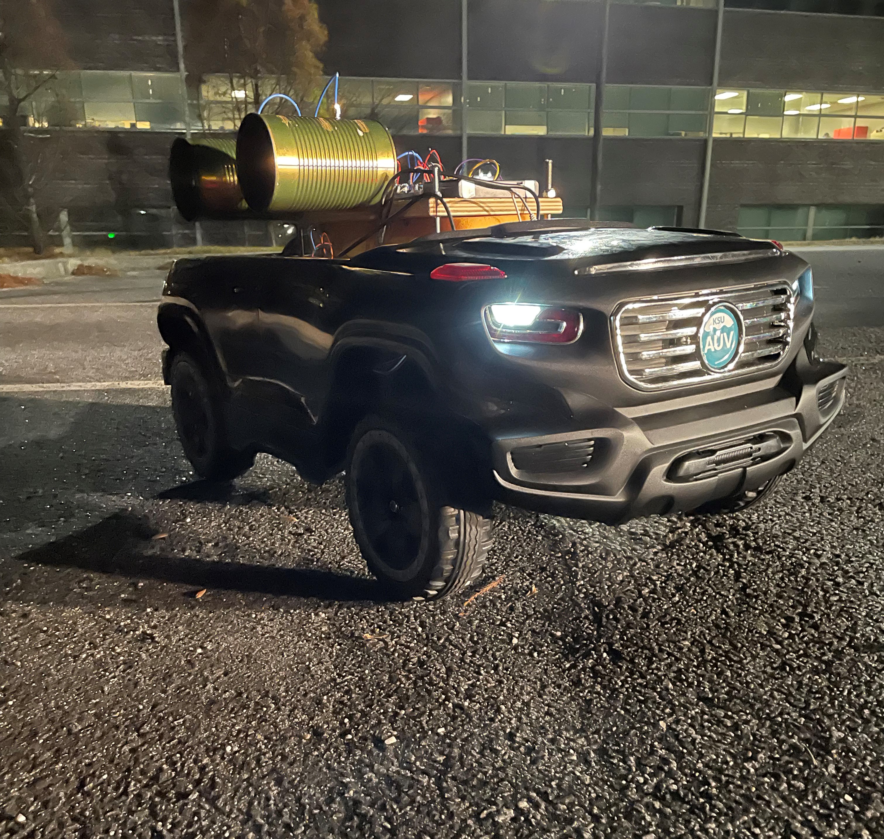
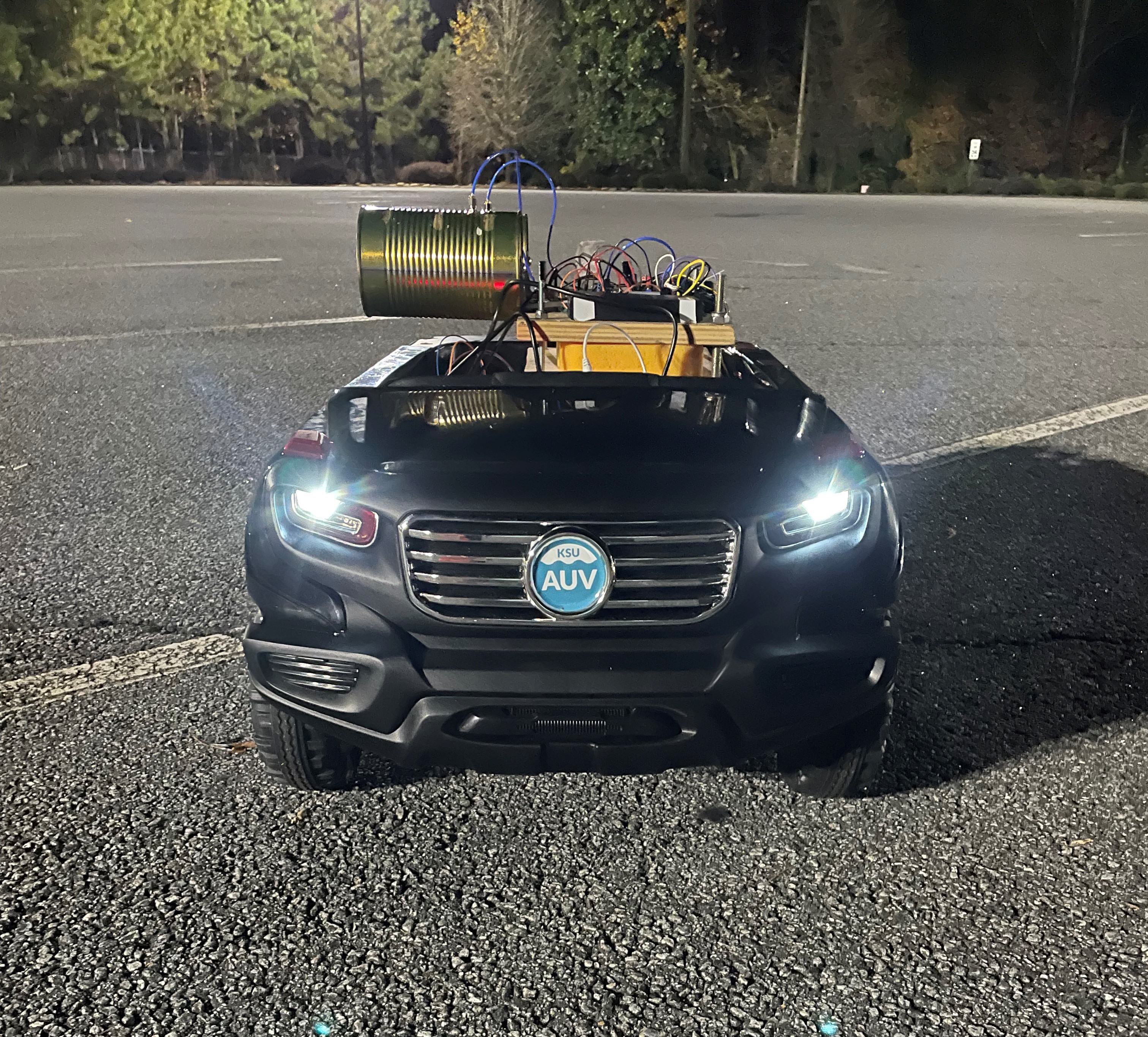
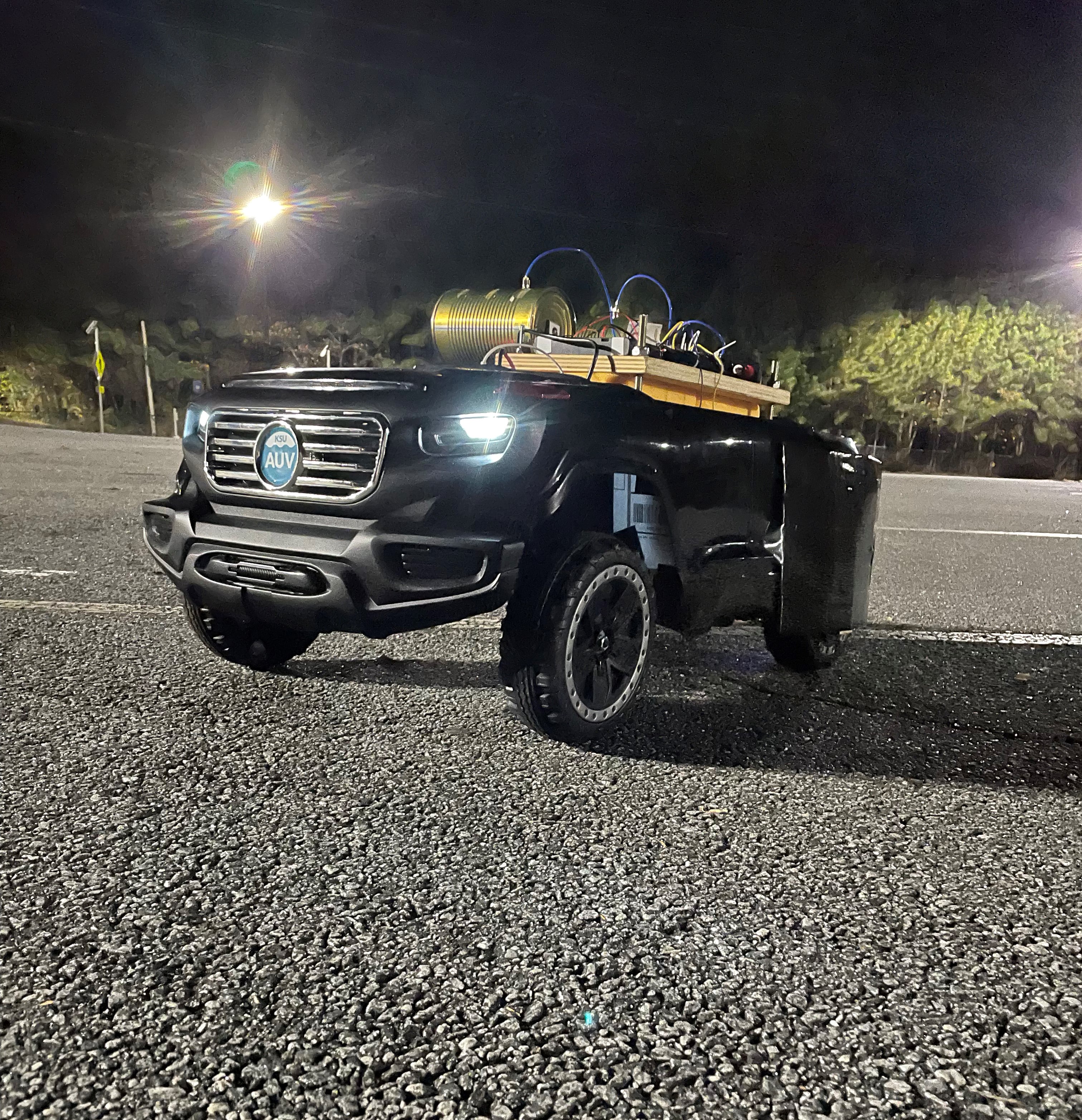
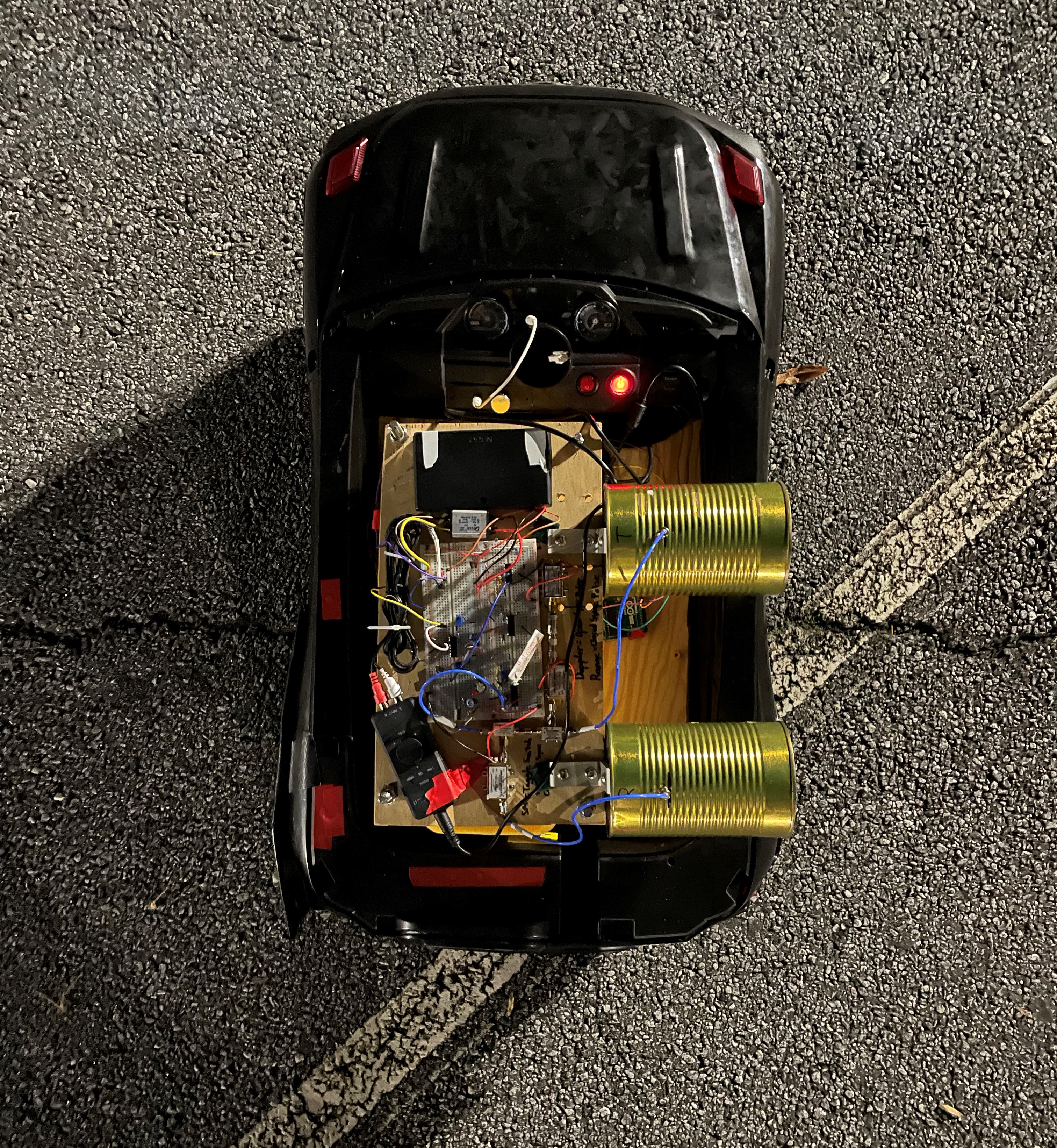
The Mobile Synthetic Aperture Radar (SAR) was my senior design project. The laptop-based SAR system can detect and determine a target’s range by using radio frequency (RF) waveforms while being transported on a mobile remote-controlled (RC) vehicle.


The code used for this project was MATLAB (waveform processing) and Arduino (vehicle movement). If you wish to download any of those pieces of code, please download the MATLAB code RIGHT HERE and the Arduino code RIGHT HERE. The code will also be located down below.


SAR Overview

Brief Project Description: The radar will travel 20 yards on the RC vehicle while processing waveforms perpendicular to the direction of the vehicle at 50 yards. The SAR device will identify the wall of the Engineering Technology Center located on the Marietta campus of Kennesaw State University, as well as other large objects in the path of the radar.


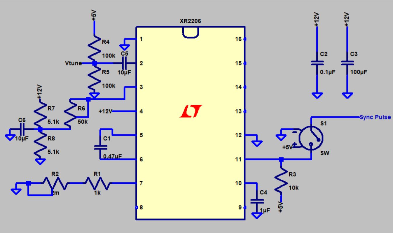
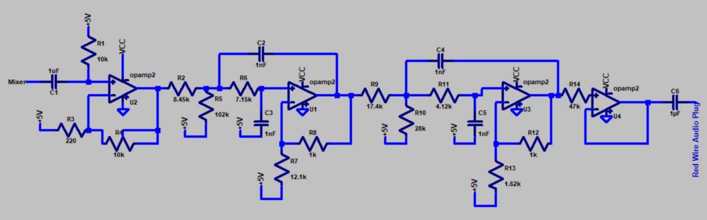
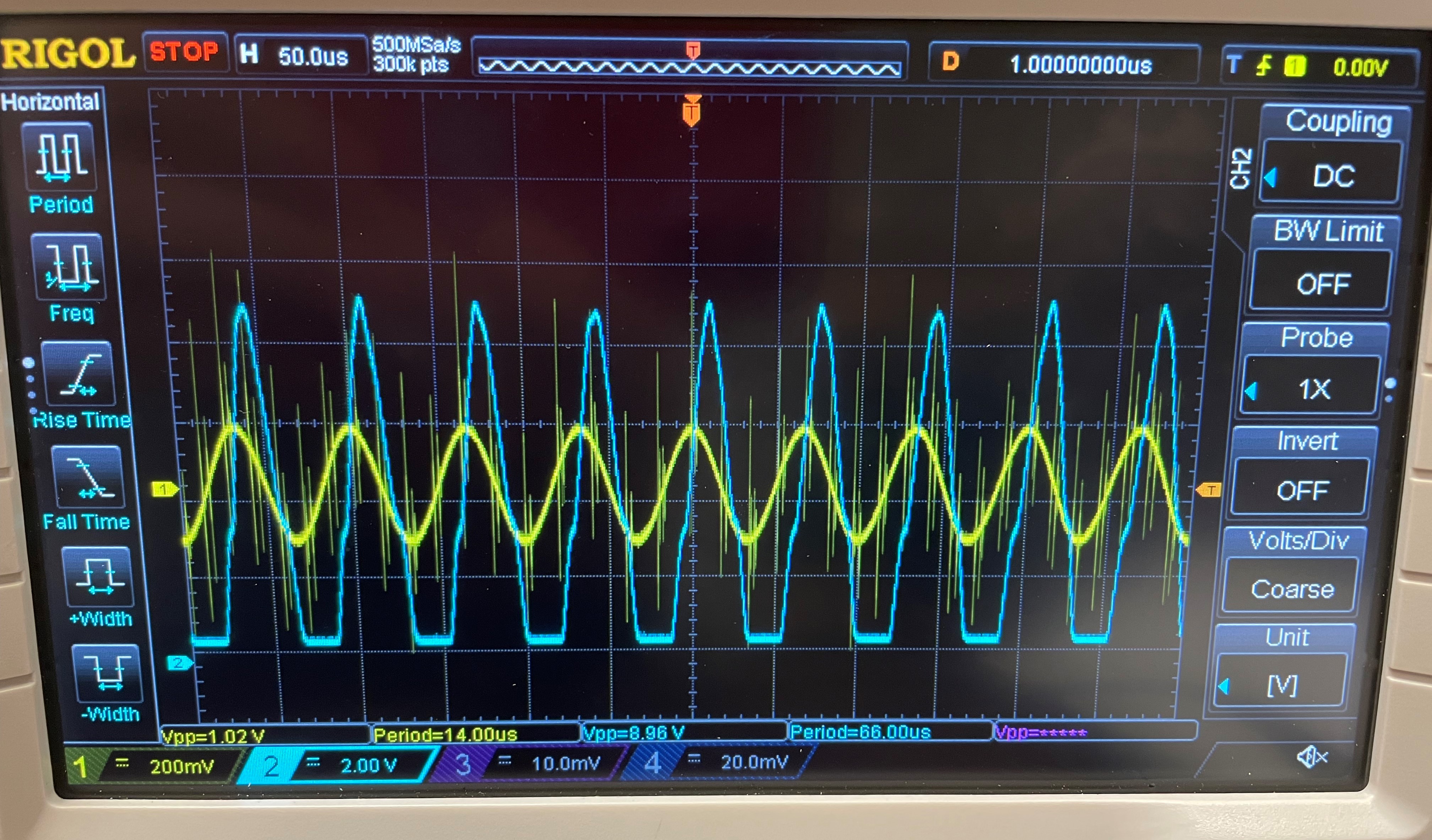
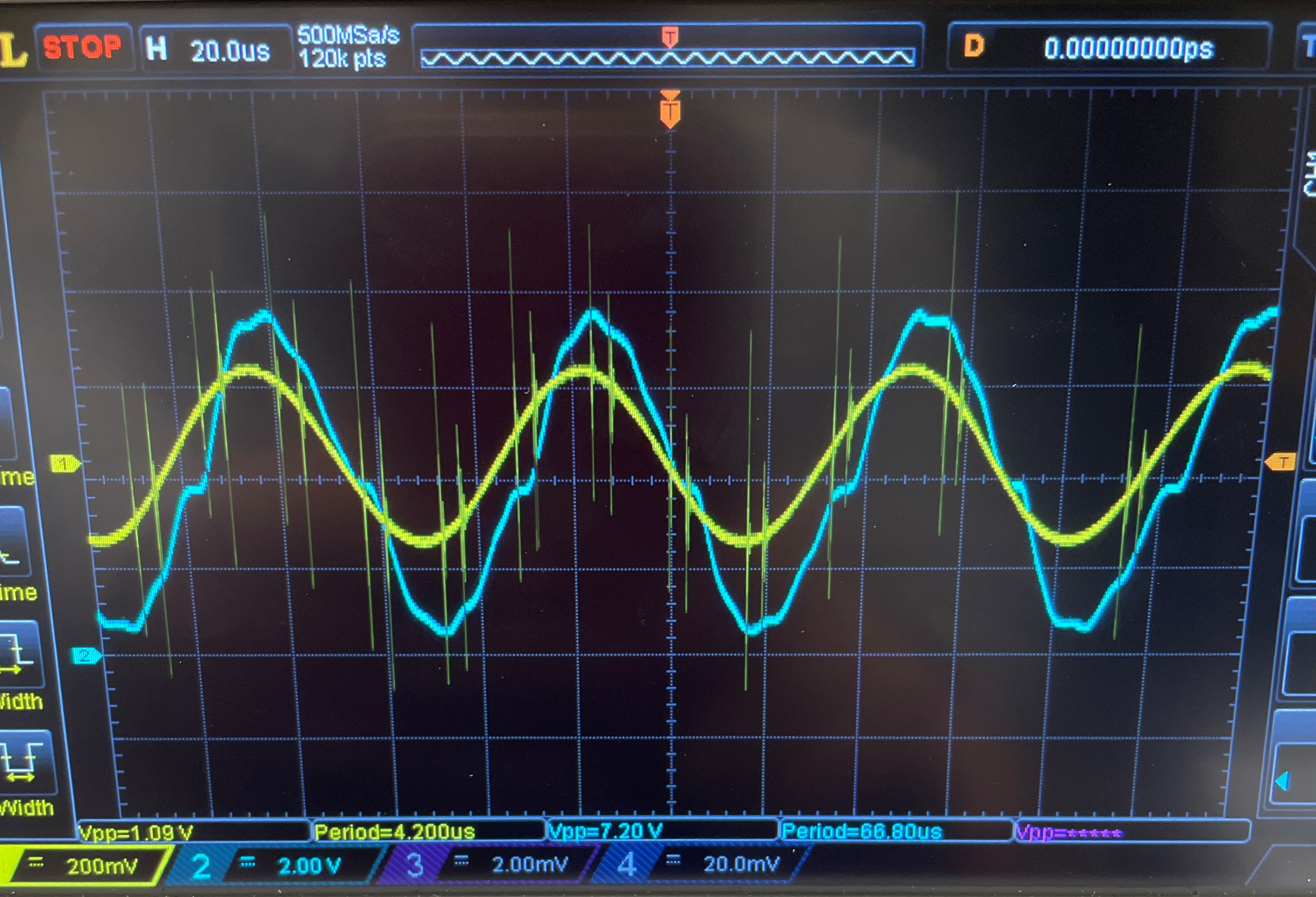
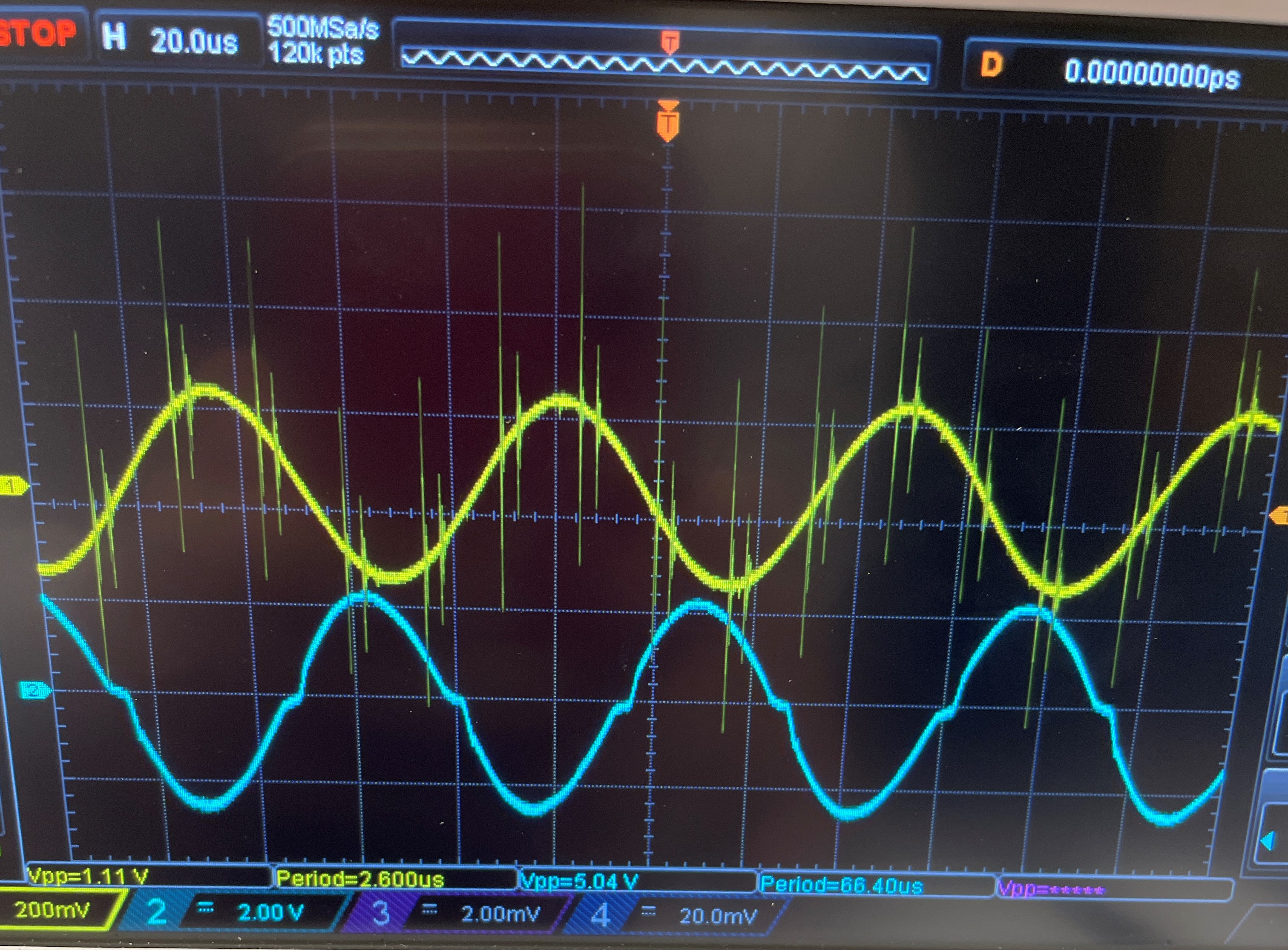
Hard Part of the Project: Understanding RF engineering was the hardest part of the project. I started the project with very minimum knowledge in RF so to catch up to speed, I had to research how radars, SARs, and RF components work. The next hardest part of the project was getting our function generator, chirping, frequency span, and sync pulse potentiometers lined up to make sure that the output waveform of our system wasn't chipping.


Slide Show of the Mobile SAR Radar

1 / 7
Front Right
2 / 7
Front View
3 / 7
Front Left
4 / 7
Top View
5 / 7
Front Right View
6 / 7
Rear View
7 / 7
Back Right View

Details of the Project

SAR Basics and Schematics

The SAR imaging device detects targets by transmitting radio frequency waves at a target and receiving the echo back. This mobile radar system has two antennas, one that transmits the RF wave and the other receives it. For the transmitter antenna, the XR-2206 chip produces a triangle wave that is sent to the Vtune portion of the Voltage Controlled Oscillator (VCO). This chip also controls the chirp rate adjuster, which controls the period of the wave that the chip produces, and the frequency span controls the frequency that is sent to Vtune. Once the signal is sent through the Vtune, the VCO, the attenuator, the amplifier sends out the transmitter antenna. Once the signal reflects off an object, then it returns to the receiver antenna.


Modulator

The modulator uses an XR-2206 chip that produces a triangle wave that is used for the Vtune transmission frequency. This wave is sent through and controls the Voltage Controlled Oscillator (VCO). The modulator also generates a sync pulse that goes directly to the left input of the sound card through the relay switch. Vtune is adjusted to have a period of 40 ms and amplitude between 2-3.5 Vpp.


Video Amplifier and Low Pass Filter

A video amplifier is needed to increase the output signal of the receiver antenna and the 15KHz low pass filter is used to avoid aliasing to the sound card so the PC can properly read the signal.

The gain stage is tested by providing the input of a 15KHz 1 Vpp sine wave by a function generator and an oscilloscope is used to verify the output. The goal is to see if the output waveform would experience clipping and adjust the 10 kΩ potentiometer so the clipping would stop. When 1 Vpp sine wave is applied, significant clipping is experienced. The output for this test is 8.98 Vpp. Adjustments to the potentiometer eliminate the clipping and the potentiometer is adjusted to make the output waveform remove clipping. The output is 7.20 Vpp.


The output of the oscilloscope is moved to the output of the LPF. The figure below shows that there is no clipping is experience within the system.

Mobile SAR In Action

MATLAB Code for Waveform Processing

Arduino Code for Vehicle Movement

Get In Touch